 Let's talk about your project ↗
TECHNICAL
Block design: cavity and port layout.
Space inside the block is limited: cavities, passages and ports share the same volume.
From the outside, designing a manifold block looks like nothing more than placing holes. In reality the cavity and port layout has to be solved together, because three things share the same volume: the valve cavities, the ports and the internal passages that connect them. A decision taken for one directly affects the other two.
Cavities are placed first
Cavities are the bulkiest element of the block; their diameter and depth depend on the valve manufacturer's standard and are not negotiable. That is why the cavity and port layout starts from the cavities. The wall allowance left between two cavities has to be large enough both to prevent breaking through during machining and to keep the material from being overstressed at working pressure.
Which face the cavities open onto is part of the cavity and port layout as well: valves gathered on the same face make maintenance easier, while valves spread over different faces make the block smaller.
Ports are positioned according to the assembly direction
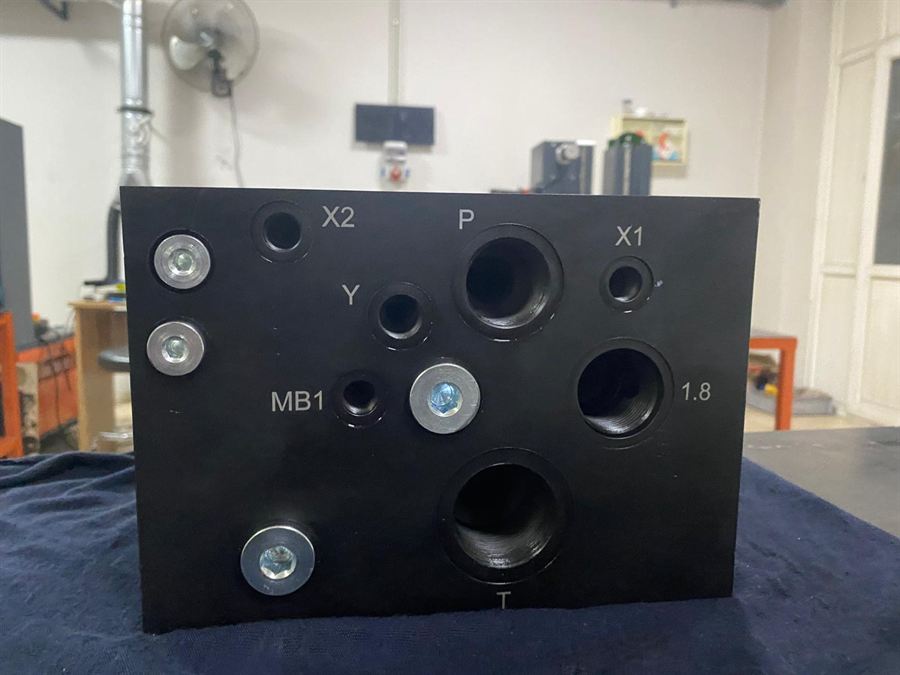
What decides the cavity and port layout is not hydraulics but assembly. The bend radius of the hose, the spanner clearance of the fitting and the direction a hand can reach during maintenance affect port position more than the hydraulic flow does. If the top face of the block faces a wall once the machine is assembled, the port there is unusable in practice.
Test and measuring ports are planned at this stage too. A pressure gauge port added later usually cuts across an existing passage.
Passages follow the most suitable path, not the shortest
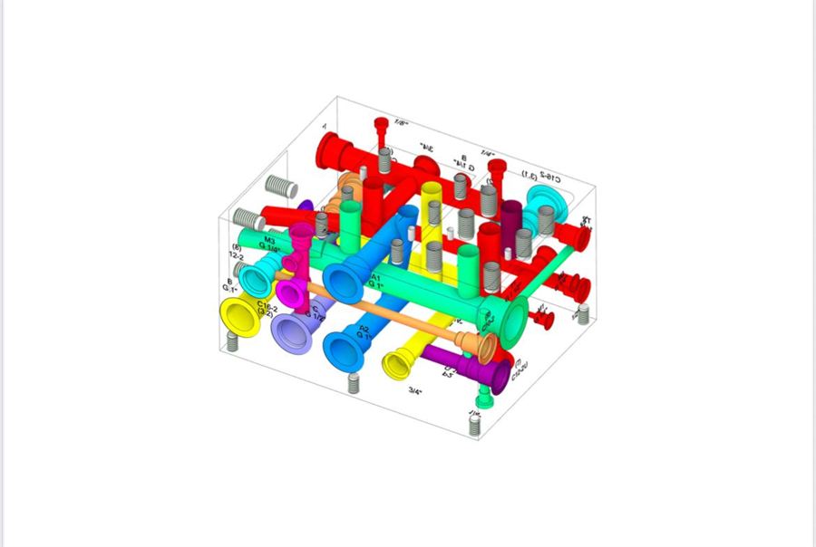
Internal passages are opened with straight holes; there is no curved passage inside a block. For this reason the connection between two points is usually built with two or three holes that intersect each other. The sharper the intersection angle, the more the fluid is forced; wide-angle intersections are preferred wherever possible.
Every hole opened to the outside during drilling is closed with a plug once its job is done. The plug is a product choice as well: its position, size and sealing type have to be settled in the design.
Blind holes and dead volumes
Air and contamination collect in the blind volumes left at the ends of passages. When the system is first started this air is compressed and lengthens the response time. Minimising dead volumes in the design also makes bleeding the air easier during commissioning.
Dimensions and tolerance
Cavity diameters and sealing surfaces are machined to a tighter tolerance than port threads. The machining tolerance we work to is ±0.02 mm; this value is decisive for the correct squeeze of the o-ring and for the valve seating fully in the cavity.
Cavity and port layout checklist
- Is the wall allowance between cavities sufficient?
- Are the ports accessible from the assembly direction?
- Are the passage intersections unnecessarily sharp?
- Have the plug positions and sizes been set?
- Is there a test/measuring port?
- Have the dead volumes been reduced?
All of these cavity and port layout decisions can be seen on the 3D model and the technical drawing before manufacturing starts. We describe the process step by step on our manifold engineering page.
Is your drawing ready?
Let us start together.
Share your hydraulic schematic or your technical drawing. Our engineering team will come back to you with technical feedback the same day.