 Let's talk about your project ↗
01 / OUR AREAS OF EXPERTISE
Hydraulic manifold engineering.
From schematic to 3D model; port layout, cavity design and flow analysis.
WHAT WE DO
We turn your schematic into a manufacturable design.
We start by assessing your hydraulic schematic and operating conditions. Once flow rate, working pressure, valve types and mounting constraints are clear, we settle from how many faces the manifold will be machined and what its dimensions will be.
We design the port layout, the internal flow passages and the valve cavities together. Passage intersections, dead volumes and needless pressure losses are eliminated at the design stage; the manifold is resolved around the mounting orientation and service access.
We submit the 3D model and the technical drawing for your approval. Once you approve, the same team machines the manifold on our own machine tools — the engineer who designed it also oversees production.
ANATOMY OF A MANIFOLD
Drilled passages
instead of hoses.
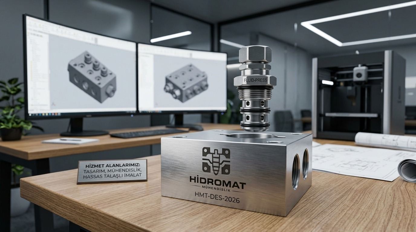
A manifold block gathers the valves and the connections in a single metal body. The five basic elements we decide on in design:
- 1Cartridge cavity
The stepped seat the valve sits in. Diameter, depth and surface finish are machined to the valve maker's cavity standard.
- 2Inlet port (P)
The threaded port where the line from the pump connects. Port type and size are chosen to the flow rate in the circuit.
- 3Internal passage gallery
The bores that link the ports and the cavities to one another. Intersections and diameters are planned to reduce pressure loss.
- 4Outlet port (A)
The line running to the cylinder or the motor. Positioned to the mounting orientation and hose access.
- 5Fitted cartridge valve
The valve screwed into the cavity. The circuit is built inside the manifold, hose-free and compact.
THE DESIGN PROCESS
An approved design
in four steps.
At the end of each step you know what came out of it and what you approved.
Schematic and requirement analysisWe assess your hydraulic schematic, working pressure, flow requirement and mounting constraints together.
Port and cavity layoutWe position the valve cavities to the maker's standard and plan the port layout around the mounting orientation and hose access.
Flow passage designWe resolve the internal passages, intersections and transition diameters so as to reduce pressure loss; we clear blind bores and dead volumes.
3D model and approvalWe submit the model and the technical drawing for your approval. After approval we move to production; if a revision is needed we go back to design.
TECHNICAL SCOPE
We work
with numbers.
The limits and outputs the design decisions rest on.
| Scope | Value | Note |
|---|---|---|
| Design output | 3D model + technical drawing | Submitted for your approval before production |
| Shared file formats | STEP, IGES, DWG | 3D model and technical drawing |
| Machining tolerance | ±0.02 mm | Checked by measurement during production |
| Test pressure | up to 350 bar | Set according to the project |
| Manifold material | Ductile iron, steel, aluminium | Selected according to the application |
| Manifold size | According to the project | We confirm feasibility the same day with your drawing |
| Technical feedback | Same day | After the drawing is shared |
FROM OUR WORK
From design
to the machine.
From schematic to 3D model: examples from our design work with the internal passages and cavities coloured.
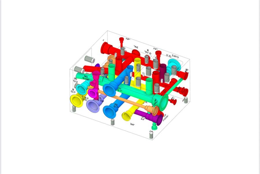 INTERNAL PASSAGES
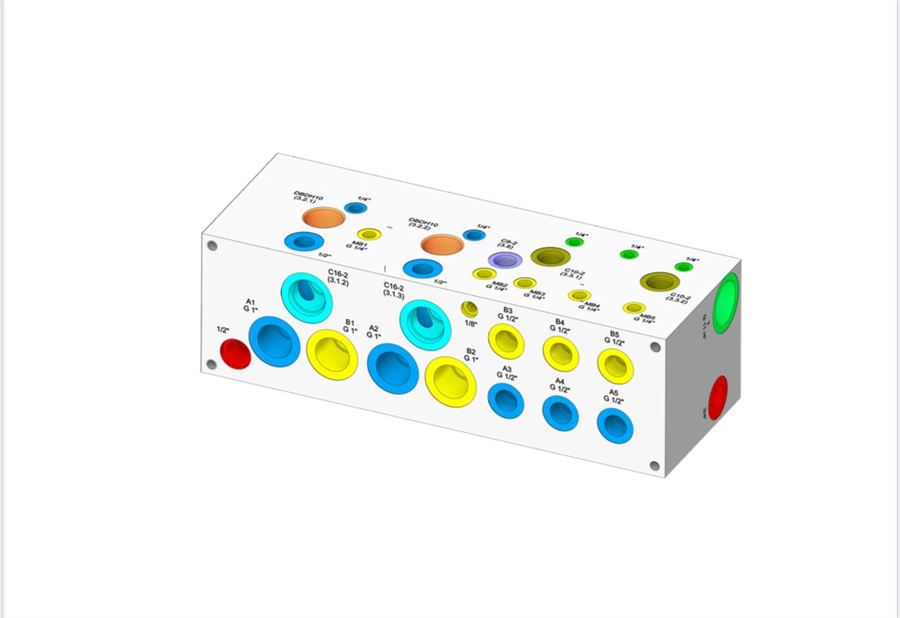 CAVITY LAYOUT
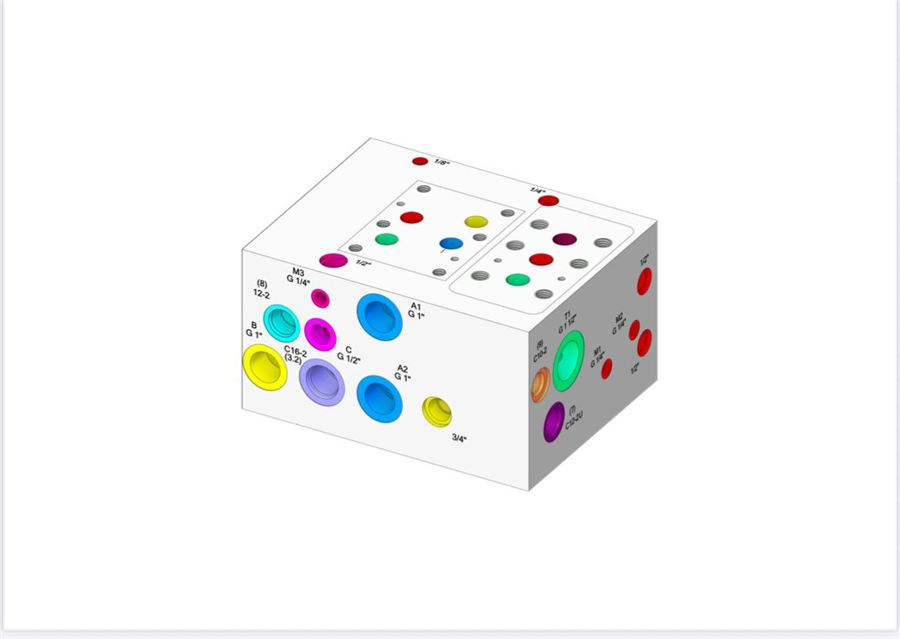 3D MODEL
FREQUENTLY ASKED
About
design.
If your question is not answered here,
contact us directly.
I only have a hydraulic schematic. Can we work together?
Yes. From the schematic we design the port layout and the cavities and submit the 3D model for your approval. Once the technical drawing is ready we move to production.
What information is needed to start the design?
A hydraulic schematic or a description of the circuit, the working pressure, the flow requirement and, if any, the mounting space dimensions are enough. If the valve make and model you will use is known, we resolve the cavities to that standard.
Do you give us the 3D model and the technical drawing?
Yes. We share the approved 3D model and technical drawing in STEP, IGES and DWG formats.
Can the design be changed after approval?
A revision is possible before production starts. That is why we submit the 3D model and the technical drawing for your approval before going into production.
RELATED SERVICES
The process does
not end here.
The manifold we design is machined, valved and tested by the same team.
 ↗PRECISION MACHINING
Precision
machining
NC drilling and grinding for repeatable production true to the drawing.
 ↗VALVES & ASSEMBLY
Cartridge valves
and assembly
Valve selection to suit your circuit, standard cavity machining and assembly kit.
 ↗TESTING & DELIVERY
Turnkey custom
manifold
A fully assembled, pressure-tested system, ready to run.
Is your drawing ready?
Let us start together.
Share your hydraulic schematic or technical drawing. Our engineering team will come back with technical feedback the same day.