 Let's talk about your project ↗
TECHNICAL
What to consider when selecting a cartridge valve.
Which catalogue figures are binding, and which decision locks all the others?
Cartridge valve selection is not a component decision on its own: the moment you choose the valve you have also chosen the cavity of the block, the machining sequence and, most of the time, the assembly direction. That is why cartridge valve selection is made at the very start of the block design.
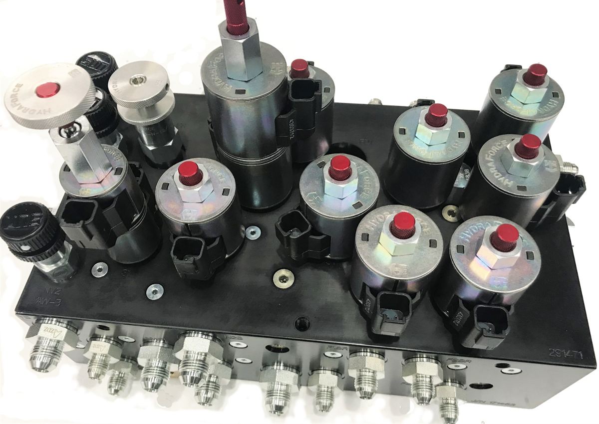
Flow rate: the working figure, not the catalogue figure
The maximum flow given in catalogues is the upper limit the valve can pass without being damaged; it is not the flow at which the circuit runs continuously. As the continuous flow approaches that upper limit, pressure loss and heating increase. In practice, choosing the valve for the flow range in which it works most often, rather than for the peak flow of the system, gives a better result.
In cartridge valve selection the flow usually grows together with the thread size in screw-in cartridges: a spool valve with a 3/4-16 UNF cavity stays around 30 l/min, while its equivalent with a 7/8-14 UNF cavity can go up to 60 l/min. For higher flows, large metric cavities or slip-in logic elements come into play.
Working pressure and the poppet–spool difference
Poppet type valves close by seating in their seat; their leakage in the closed position is very low and they generally allow higher pressure. Spool valves, on the other hand, always leak a certain amount because of the clearance between the spool and the body. In circuits where a load is to be held and the cylinder has to stay in the same position for hours, the poppet type is preferred.
Manufacturers state this difference clearly in their catalogues: for poppet valves, operation up to 420 bar on all ports and leakage figures of no more than a few drops per minute are given, while for spool valves the limit is generally around 350 bar.
Cavity standard: a decision with no way back
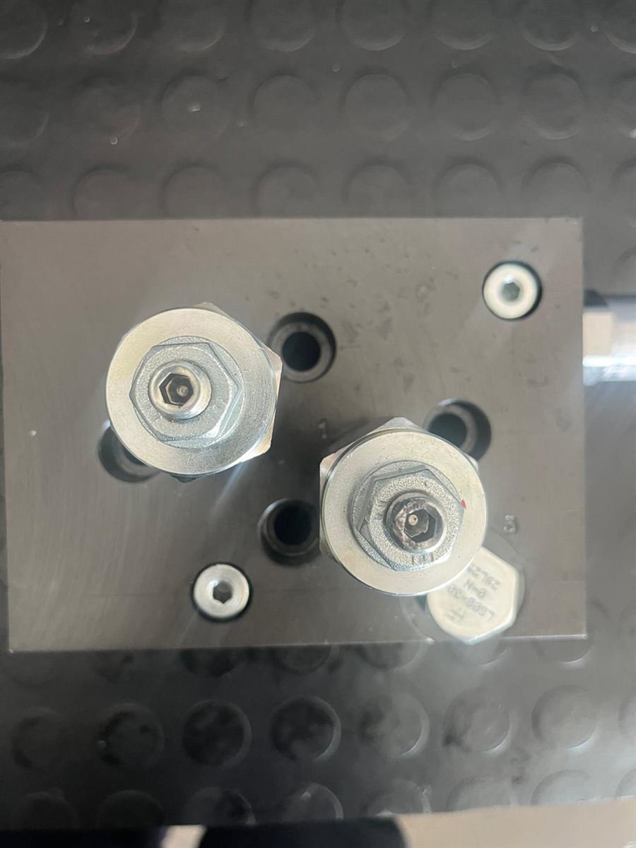
Every valve has its own cavity standard, and that standard is machined into the block. The ones most often met in screw-in cartridges are 3/4-16 UNF (SAE 08) and 7/8-14 UNF (SAE 10), together with the M20×1.5, M26×1.5 and M35×1.5 metric threads. In high-flow industrial circuits, slip-in cavities to ISO 7368 are used.
Once the cavity has been machined, moving to a valve of a different standard usually means remanufacturing the block. For this reason cartridge valve selection, down to brand and model, has to be settled before block manufacturing begins.
Function and symbol
The ISO 1219 symbol in the circuit diagram describes what the valve will do: relief, pressure reducing, check, throttling, load holding, directional control. The adjustable and fixed, pilot operated and direct acting versions of the same function behave differently. For cartridge valve selection, if there is an adjustment arrow next to the symbol in your schematic, the valve you choose has to be adjustable too.
The coil in electrically operated valves
In solenoid operated cartridges the coil voltage (commonly 12 V or 24 V DC), the connector type and the protection class are stated separately. The coil is a part that can be ordered independently of the valve body; when planning spares it has to be treated as a separate item.
Cartridge valve selection checklist
- The continuous flow of the circuit and the peak flow
- Working pressure and peak pressure
- Is a load being held? (poppet / spool decision)
- Cavity standard and thread size
- Adjustment range and adjustability
- If electrical, coil voltage and connector type
- Fluid type and operating temperature
Running cartridge valve selection and block design together removes most of the revisions made afterwards. You can find the process on our cartridge valve and assembly page, and the product families we work with on our brand pages.
Is your drawing ready?
Let us start together.
Share your hydraulic schematic or your technical drawing. Our engineering team will come back to you with technical feedback the same day.